Using the LM57A Temperature Sensor
 I looked at using several different temperature sensors for this project, and settled on the LM75A Temperature Sensor High-speed 12C Interface Development Board Module
 . I chose the LM75A for several reasons, including cost, on-board analog-to-digital conversion, I2C interface, and ability to hard-wire the I2C address into the chip. For those of you who would rather not read through my personal experience with the LM57A, here is a link to the data sheet. For less than $3 US, this is an amazing little device, and has way more features than we will be using here. You can actually set temperature thresholds on the chip itself, and use it as a thermostat without even involving the Pi, but enough about features we won't be using. I'll try to focus on the features that make this the perfect temperature sensor for this project.
 The most important feature of this sensor, is that it has built-in analog-to-digital conversion, so it can send data directly to the Raspberry Pi, which is limited in only having digital GPIO pins. I was also looking for something with an I2C interface, which I will cover more in-depth in the next section. The nice thing about I2C is that you can connect multiple devices on the same 2-wire serial connection. In order for this to work, each device must have a unique 7-bit address, which is where another feature of the LM57A comes in handy. You can set the last three bits of the address by connecting the solder pads for A0 through A2 on the back of the PCB. The first four bits of the address are '1001', and are hardwired inside the chip, so that gives us the option to use the addresses '1001000' through '1001111', which are the Hex addresses 0x48 through 0x4F. With these 8 potential addresses we can hook up 8 of these sensors on one I2C circuit. In the picture above you can see that the configuration of the pads makes it easy to set the address using a simple solder bridge. The chip on the left is unset. The chip in the middle is set to 1001001 (0x49) and the chip on the left is set to 1001011 (0x4B). These registers must be set, and should not be left floating during use.
One last feature of the LM57A that adds a little bit of convenience to this project is that the input voltage can range from 2.8V to 5.5V. This means that we can power these little units with either the 3.3V or 5V rail on the Pi. If it was just the sensors the 3.3V rail would suffice, but since we are also going to be powering a 7-segment LED from the same source, and the 3.3V on the Pi is limited in the amount of current it can supply, we'll go ahead and use the 5V supply on the Pi, which is wired directly to the USB power source, and is only limited by the power supply that you are using for your Pi.
Setting-up and Using I2C Protocol with the Raspberry Pi
 |
| The image above is borrowed from https://www.lammertbies.nl/comm/info/I2C-bus.html |
Now that I've discussed why I am using I2C, let's get to how to set up I2C on the Raspberry Pi. Adafruit has a nice tutorial (link), but unfortunately it is out of date and doesn't work with the latest versions of Raspbian. So, here is my own updated tutorial on enabling and testing I2C.
By default I2C is not enabled, so first we need to enable it. This can be done the easy way using raspi-config, options 5, then option P5, but I prefer to understand what is happening under the hood, so let's go over how to quickly do this via the CLI. First we need to edit the /etc/modules file to tell the Pi to load the I2C kernel module on boot. Open /etc/modules with a text editor and add the following two lines to the end of the file:
i2c-bcm2708
i2c-dev
Next we need to edit the /boot/config.txt file. Open /boot/config.txt with a text editor and uncomment the following line by removing the pound sign:
#dtparam=i2c_arm=on
And that's it. I2C is now enabled. Next we want to install the python module and command line utility that will enable us to utilize I2C.
sudo apt-get install python-smbus
sudo apt-get install i2c-tools
OK, we are ready to test this out. Hookup one of the LM57A sensors to the Pi. The I2C-1 SDA and SCL pins are on GPIO pins 3 and 5 respectively, and we will also need to to use a 3.3V and Ground pin to power the sensor. To test to see if the Pi can see the sensor use the command i2cdetect -y 1, where the 1 refers to the specific I2C bus we are using. On older models of the Pi this will be 0 instead of 1.
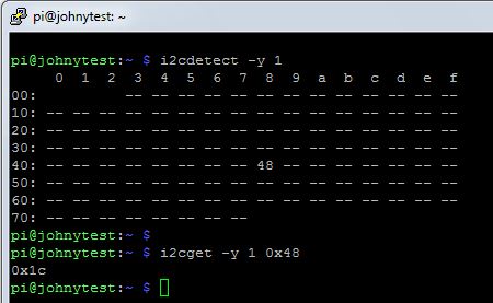
In the image to the left, you can see that the Pi has detected the temperature sensor with an address of 0x48. On this particular sensor I have set A0, A1, and A2 to 0, so the full address should be 1001000 as explained above. If we convert this to hexadecimal we get the number 48, which means everything is working as expected. Next lets see if we can pull a temperature reading from the sensor. For this we use the command i2cget -y 1 0x48, where 1 is the name of the I2C bus, and 0x48 is the address of the device we are polling. As you can see, the sensor returned a value of 0x1c. At first glance this may not seem like a usable temperature value, but lets think about this for a second. First, this is a hex value, but most of us think in decimal. If we convert 0x1c to decimal we get 28. If you are in the United States like I am, we are also not used to thinking in Celsius, so we need to convert 28 degrees C to Fahrenheit, and we get 82.4 degrees F. It's a warm day and I have the shop door open, so I am willing to accept that as an accurate reading.
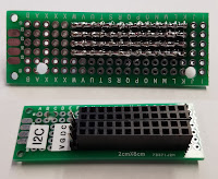
So, now we can detect an I2C slave device, and take a reading from it, but the whole point of using I2C is that we can hook up multiple devices to the same two-wire serial bus. Since we only have one set of pins on the Pi to connect to the bus we are going to have to whip up a quick circuit board to connect multiple devices. This can be done by soldering some pin headers on a circuit board and using solder bridges to connect the pins. Be sure to use a multi-meter to make sure all the rows are properly bridged, and that none of the rows are bridged together.
And that's it. I2C is now enabled. Next we want to install the python module and command line utility that will enable us to utilize I2C.
sudo apt-get install python-smbus
sudo apt-get install i2c-tools
OK, we are ready to test this out. Hookup one of the LM57A sensors to the Pi. The I2C-1 SDA and SCL pins are on GPIO pins 3 and 5 respectively, and we will also need to to use a 3.3V and Ground pin to power the sensor. To test to see if the Pi can see the sensor use the command i2cdetect -y 1, where the 1 refers to the specific I2C bus we are using. On older models of the Pi this will be 0 instead of 1.
In the image to the left, you can see that the Pi has detected the temperature sensor with an address of 0x48. On this particular sensor I have set A0, A1, and A2 to 0, so the full address should be 1001000 as explained above. If we convert this to hexadecimal we get the number 48, which means everything is working as expected. Next lets see if we can pull a temperature reading from the sensor. For this we use the command i2cget -y 1 0x48, where 1 is the name of the I2C bus, and 0x48 is the address of the device we are polling. As you can see, the sensor returned a value of 0x1c. At first glance this may not seem like a usable temperature value, but lets think about this for a second. First, this is a hex value, but most of us think in decimal. If we convert 0x1c to decimal we get 28. If you are in the United States like I am, we are also not used to thinking in Celsius, so we need to convert 28 degrees C to Fahrenheit, and we get 82.4 degrees F. It's a warm day and I have the shop door open, so I am willing to accept that as an accurate reading.

So, now we can detect an I2C slave device, and take a reading from it, but the whole point of using I2C is that we can hook up multiple devices to the same two-wire serial bus. Since we only have one set of pins on the Pi to connect to the bus we are going to have to whip up a quick circuit board to connect multiple devices. This can be done by soldering some pin headers on a circuit board and using solder bridges to connect the pins. Be sure to use a multi-meter to make sure all the rows are properly bridged, and that none of the rows are bridged together.
Using the Adafruit I2C Backpack for 7-Segment Display
 Adafruit makes a very handy little device called the backpack that takes I2C in and uses that to drive an LCD array. For this project we are using the model HT16K33 that works with a 4-digit 7-segment display
 . As always, Adafruit provides a nice tutorial (Here and Here) for getting this thing working, so I don't feel the need to go into great detail, but I'll outline the general process and we'll test it out.
First we need to solder the backpack onto the 7-segment LED display. This is pretty self-explanatory, just be sure not to solder it on upside-down. There is a stencil on the backpack that matches the display to help with orientation. Next we need to solder on the pin headers for the two serial wires plus Vcc and GND. With the male pin headers sticking out the back of the backpack, we can stick the backpack directly on the homemade I2C bus we just created.
To get this thing working I downloaded the software recommended by Adafruit:
sudo apt-get install -y git build-essential python-dev python-smbus python-imaging python-pip python-pil
and then:
git clone https://github.com/adafruit/Adafruit_Python_LED_Backpack.git
cd Adafruit_Python_LED_Backpack
sudo python setup.py install
 Once that is done, inside the /Adafruit_Python_LED_Backpack folder you just created, there is a folder called /examples which contains well documented code that will give you a thorough understanding of how to use these modules in Python. If only every hardware maker was as thorough as Adafruit we could save so much time. You can run these example scripts to make sure that your Backpack and 7-segment display are working correctly.
 One last trick I'd like to mention regarding the 7-segment display being used for this project is that while this unit can only display numbers, it is able to display hexadecimal numbers, which gives it the ability to display the letters a through f. I wanted to be able to display which area each temperature correlated to, so I needed to be able to write the strings "Cab1", "Cab2", and "Base" for basement. Luckily the only letter in those labels that is not able to be represented in hex is "s". Luckily there is no difference between 5 and S on a 7-segment display, so that is how I was able to make it display the necessary strings.
Controlling Fans Using the Raspberry Pi
 Turning on the cooling fans for the network cabinets is the easy part. Since I am using 12V fans they will need to be powered by an external power source and controlled by a relay wired to a GPIO pin. If you are using a relay board similar to the one I am using (JBtek 4 Channel DC 5V Relay Module
 ), then there is no additional circuitry required between the Pi and the board because the relay board already contains a resistor and an opto-isolator to prevent too much current from being drawn from the GPIO pin. Just be sure to power the relay board with one of your 5V pins wired to Vcc on the board.
 If you have followed any of my previous projects, you may know that I have already set-up a 12V (30 amp) power supply, a DC fuse panel, and a relay board for use with my automated sprinklers, so there was nothing for me to purchase other than the fans. I wired the 12V power supply, through the fuse panel, to a switch to allow me to turn off the power to both sets of fans. I wired the output of the switch to two relays so that I could control the fans in the two cabinets separately. From the relays I ran 16 awg wire to the top of each cabinet where the fans would be mounted. The fans I purchased had old IDE-style power connectors. I like to keep things modular, so in order to make replacing the fans easy in the future, I cut some power connectors off of an old PSU, and soldered them onto the ends of the 16 awg wires.
Final Python Script
I glossed over using I2C with Python earlier in this post because I'm doing my best to keep these posts as short as possible while still including as much information as possible. Below I have pasted the entire Python script for this project so that anyone that would like to use the script can copy and paste it. In addition I have done my best to thoroughly comment the script, so that anyone with a basic understanding of Python syntax should be able to follow along and see exactly how I used Python to send and receive data on the I2C bus. If anyone has trouble understanding the code, or if you have problems adapting the code to your own project, feel free to leave questions in the comment section below.
Of course, I've edited out my email addresses and password in the code, so if you are going to copy&paste it, be sure to substitute in your own email addresses and the password for the sending email account.
Of course, I've edited out my email addresses and password in the code, so if you are going to copy&paste it, be sure to substitute in your own email addresses and the password for the sending email account.
#!/usr/bin/env python

###############################################################
#                                                             #
# i2ctemp2-0.py                                               #
# written by James Campbell                                   #
# July 2017                                                   #
#                                                             #
# Monitor temperatures of network and server cabinets         #
# Display temperatures and time on 7-segment display          #
# If temperatures reach preset threshold then turn on fans    #
# If temperatures reach second threshold then send email      #
# Store temperatures to log file                              #
#                                                             #
###############################################################


import time
import smbus  # lets us access the i2c bus
from Adafruit_LED_Backpack import SevenSegment # used to control 7-segment display
import RPi.GPIO as GPIO  # used to read/write to GPIO pins
import datetime
import smtplib  #used to send email
from email.mime.text import MIMEText  #used to compose email


CAB_1_TEMP = 0x48 # I2C address for Cab 1 temp sensor
CAB_2_TEMP = 0x49 # I2C address for Cab 2 temp sensor
BASEMENT_TEMP = 0x4B # I2C address for basement temp sensor
DISPLAY = 0x70 # I2C address for 7-seg display
BUS_NUM = 1 # 1 is the I2C bus (board pins 3 and 5)
PAUSE_TIME = 3 # the number of seconds to pause on each display
FAN1_PIN = 13 # GPIO Pin to control fan relay for Cab 1
FAN2_PIN = 19 # GPIO Pin to control fan relay for Cab 2
FAN_THRESHOLD = 90 # the temperature threshold (F) for turning on fans
EMAIL_THRESHOLD = 95 # the temperature threshold (F) for sending an email
GMAIL_USER = 'youremail@gmail.com' # email account used to send email
GMAIL_PASS = 'yourpassword' # password for email account used to send email
SENT_FROM = GMAIL_USER
SEND_TO = 'email1@email.com, email2@email.com' # email recipient for alerts
FAN1_RUNNING = False
FAN2_RUNNING = False
EMAIL_TIMER_1 = 0
EMAIL_TIMER_2 = 0
EMAIL_TIMER_B = 0
# FAN_THRESHOLD = 50 # Uncomment this line to test the fans
# EMAIL_THRESHOLD = 50 # Uncomment this line to test the email


def CtoF( Ctemp ):
        return((Ctemp*9.0/5.0)+32) # this line converts the Celcius temperature passed
                                   # to the funtion to Fahrenheit and returns it.

def GET_TEMPS():
        global Ftemp1
        global Ftemp2
        global FtempB

 # below is an example of how to read data from an I2C bus
 # where "bus" has already been defined in the main program
 # using "bus = smbus.SMBus(BUS_NUM)".  This will return 1 byte.
        Ctemp1 = bus.read_byte(CAB_1_TEMP)
        Ctemp2 = bus.read_byte(CAB_2_TEMP)
        CtempB = bus.read_byte(BASEMENT_TEMP)

 # the lines below use the CtoF() Function defined above to
 # convert Celcius to Fahrenheit
        Ftemp1 = CtoF(Ctemp1)
        Ftemp2 = CtoF(Ctemp2)
        FtempB = CtoF(CtempB)

        # the below is just for troubleshooting
        print ('The follwoing temperatures have been read')
        print '%d, %d, and %d' % (Ftemp1, Ftemp2, FtempB)


def FAN_CHECK():  # This function compares cabinet temps to
                  # thresholds and turns the fan on or off.
        global FAN1_RUNNING
        global FAN2_RUNNING

        if FAN1_RUNNING:
                if Ftemp1 < (FAN_THRESHOLD - 3):
                        GPIO.output(FAN1_PIN, 1)
                        FAN1_RUNNING = False
        else:
                if Ftemp1 > FAN_THRESHOLD:
                        GPIO.output(FAN1_PIN, 0)
                        FAN1_RUNNING = True

        if FAN2_RUNNING:
                if Ftemp2 < (FAN_THRESHOLD - 3):
                        GPIO.output (FAN2_PIN, 1)
                        FAN2_RUNNING = False
        else:
                if Ftemp2 > FAN_THRESHOLD:
                        GPIO.output (FAN2_PIN, 0)
                        FAN2_TIMER_RUNNING = True

        print ('fan check') # for troubleshooting only


def DISPLAY_TEMP( temp, cab_num ): # in this function we will write data
                                   # to the I2C Backpack 7-segment display
                                   # The value for "display" has already been
                                   # set in the main program to refer to the
                                   # bus and address for the 7-seg display

        display.clear() # This clears the display.  If this is not done, any
                        # data that is not overwritten will remain. The display
                        # will not actually clear until .write_display() is called

        display.set_colon(False) # This uses a boolean value to specify if the
                                 # colon is displayed, as in a digital clock

        display.print_hex(cab_num) # This is how you display a hex number on
                                   # the display

        display.write_display() # Once whatever is going to be displayed is set
                                # This line actually sends it to the display

        print ('displaying %s' % hex(cab_num)) # for troubleshooting only

        time.sleep(PAUSE_TIME/2) # This line pauses before changing the display

        display.clear() # Just like above, this line clears the display

        display.print_float(temp, decimal_digits=1) # this line displays the value
                                                    # temp with one digit after
                                                    # the decimal point

        display.write_display() # Just like above, this line actually sends the
                                # data to the display

        print 'displaying temp' # for troubleshooting only

        time.sleep(PAUSE_TIME) # This line pauses before changing the display


def DISPLAY_CLOCK(): # This function will also write to the 7-segment display
                     # but this time instead of cabinet and temperature
                     # it will display the current time.  This will also show you
                     # how to write each specific digit seperately

 # Below is one of the two ways we will use in this script to get the
 # current time.
        now = datetime.datetime.now()
        hour = now.hour
        minute = now.minute

        if hour > 12:
                hour = hour - 12 # This converts 24 hour time to 12 hour time

        display.clear() # Just like above this will clear the display.

 # Below we are setting the digits one at a time.  They are numbered
 # 0 through 3, with 0 starting on the left and 3 ending on the right.

        if (hour / 10) > 0: # These two lines keep 6:00 from showing up as 06:00
                display.set_digit(0, int(hour / 10))

        display.set_digit(1, hour % 10) # this uses modulo to set the second digit
                                        # for hour

        display.set_digit(2, int(minute / 10)) # this line sets the first digit for
                                               # minute by dividing minutes by 10 and
                                               # dropping the remainder

        display.set_digit(3, minute % 10) # this uses modulo to set the second
                                          # digit for minute

        display.set_colon(True) # This line turns on the colon on the display

        display.write_display() # As before, this line actually sends the data to
                                # the 7-seg display

        print 'displaying time' # for troubleshooting only

        time.sleep(PAUSE_TIME) # This line pauses before changing the display again


def SEND_EMAIL ( location, temperature ): # This function sends an email

        timestamp = time.strftime("%m-%d-%y %H:%M:%S")
        subject = '%s Temperature Too High' % (location) + timestamp
        body = 'The temperature in %s is %d degrees.' % (location, temperature)

        msg = MIMEText(body)
        msg['From'] = SENT_FROM
        msg['To'] = SEND_TO
        msg['Subject'] = subject

        try:
                server = smtplib.SMTP_SSL('smtp.gmail.com', 465)
                server.ehlo()
                server.login(GMAIL_USER, GMAIL_PASS)
  server.sendmail(SENT_FROM, SEND_TO, msg.as_string())
  server.close()

                print 'email sent' # for troubleshooting only
        except:
                print 'email atempted and failed' # for troubleshooting only


def EMAIL_CHECK ():
 # This function decides if an email should be sent, and calls SEND_EMAIL() if so.
 # I don't want to spam myself with emails, so the two conditions for emailing
 # are that the temperature is above the threashold, and an email has not been
 # sent in the last 15 minutes

        global EMAIL_THRESHOLD
        global EMAIL_TIMER_1
        global EMAIL_TIMER_2
        global EMAIL_TIMER_B

        print 'email check' # for troubleshooting only

        if Ftemp1 > EMAIL_THRESHOLD and time.time() > (EMAIL_TIMER_1 + 900):
             SEND_EMAIL ('Network_cabinet_1', Ftemp1)
             EMAIL_TIMER_1 = time.time() #reset email timer
             print 'ending email for cab1' # for troubleshooting only

        if Ftemp2 > EMAIL_THRESHOLD and time.time() > (EMAIL_TIMER_2 + 900):
             SEND_EMAIL ('Server_cabinet_2', Ftemp2)
             EMAIL_TIMER_2 = time.time()
             print 'sending email for cab2' # for troubleshooting only

        if FtempB > EMAIL_THRESHOLD and time.time() > (EMAIL_TIMER_B + 900):
             SEND_EMAIL ('Basement', FtempB)
             EMAIL_TIMER_B = time.time()
             print 'sending email for basement' # for troubleshooting only


def WRITE_TO_FILE():
        print 'writing to file' # for troubleshooting only
        timestamp = time.strftime("%y-%m-%d %H:%M:%S") # the is the second way we
                                                       # have used in this script
                                                       # to get the current date/time

        f=open('/mnt/usb/temperature.txt', 'a') # this opens a file for writing.
                                                # the 'a' means append, which will
                                                # add anything written to the end
                                                # of the file.

        # The line below writes to the file we are appending
        f.write('%s cab1 %d cab2 %d basement %d\n' % (timestamp, Ftemp1, Ftemp2, FtempB))
        f.close() # This closes the file we just appended.


# Begining of Program

bus = smbus.SMBus(BUS_NUM) # sets the variable bus to refer to I2C bus 1

# The line below sets the variable display to refer to our specific
# 7-segment display by address and bus number.
display = SevenSegment.SevenSegment(address=DISPLAY, busnum=BUS_NUM)

GPIO.setwarnings(False) # turns off GPIO warnings to terminal
GPIO.setmode(GPIO.BCM)  # sets mode for GPIO pins to BCM
GPIO.setup(FAN1_PIN, GPIO.OUT)  # sets relay 1 control pin as output
GPIO.setup(FAN2_PIN, GPIO.OUT)  # sets relay 2 control pin as output

GPIO.output(FAN1_PIN, 1)  # sets relay 1 control pin to high (relay open)
GPIO.output(FAN2_PIN, 1)  # sets relay 2 control pin to high (relay open)

display.begin()  # initializes 7-segment display

while True:  # infinite loop which will run the functions listed below
      # in that order and then repeat
        GET_TEMPS()
        FAN_CHECK()
        EMAIL_CHECK()

 # For the three lines below, the hex value is how I am displaying the
 # label strings to the seven segment display for cab1, cab2, and basement.
        DISPLAY_TEMP( Ftemp1, 0xCAB1 )
        DISPLAY_TEMP( Ftemp2, 0xCAB2 )
        DISPLAY_TEMP( FtempB, 0xBA5E )

        DISPLAY_CLOCK()
        WRITE_TO_FILE()
Final Result
So we put together the hardware and the software, and we end up with a functional device. Here is the result of the project. When the temperature in the cabinets rises above 90 degrees the fans will turn on. They will stay on until the temperature drops back below 88. If the temperature continues to rise above 95 degrees the device will email me with the current temperatures. All temperatures are recorded in a log file along with a time-stamp so that I can review the temperature data at any time.


 to control the water flow. You can buy a plastic one cheaper, but I had reservations about connecting a plastic water valve to my plumbing. Basically all I needed to do was to connect a GPIO pin from the Pi to a relay that could then switch on/off the 12V power supply to the valve. I went with a


 wired to a GPIO pin and a short Python script. I used a typical pull-up resistor configuration for the button. If you have never done this before use the diagram is to the right. The Python script will use the RPi.GPIO module to set edge detection on the GPIO pin, and then use a threaded callback function to initiate shutdown. To do the actual shutdown I will use the Python module os to interact directly with the operating system. The code is short and sweet. Feel free to copy or republish it. Here it is:


